I finally finished creating all of the button label images for the new display size. Now it was time to actually put them on the micro SD cards in the displays. This is a bit of a process since the SD cards are not accessible without removing the large circuit board.
I also added some arcade games that were not there before, so I will have to update the code on all the Arduinos as well, but I’ll save that for the next post.
In the meantime, here is a time-lapse video of me updating the SD cards. The entire process took about an hour.
I tested it to make sure everything was still working. Here are a couple of photos of the PlayStation images. Note that Start and Select are no longer upside down.
I have to say that as good as these photos look, the displays look much better in person. I loaded a few other emulators just to see how the labels looked, and I am extremely pleased with the results.
There are several connections to the control panel. Besides the power and HDMI connections to the Pi, there is the power connection for the displays, the connection to the relay for AC power, and the power button. I wanted all of these connections to be pluggable for ease of maintenance.
Because of the layout of components on the panel, I needed 90-degree connectors for the power and HDMI connections on the Pi.
The power supply that I bought for the displays came with a barrel connector, so I will use that. I glued it to the control panel to eliminate stress on the electrical connections.
That left the AC power connection and the pushbutton. I wanted the connectors to all be different to make it impossible to, for example, connect 120VAC to the GPIO pins. For the AC, I used a connector that is commonly used for power cords:
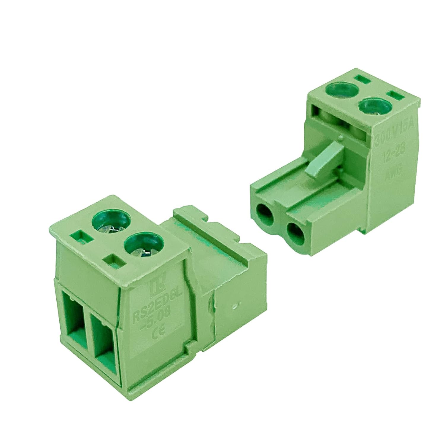
For the power button, I chose these pluggable screw terminals:
In order to make the AC connector fit, I had to cut off most of the flange. Here is an image of the control panel with all the connectors glued down and connected.
When the arcade is completely built, I want it to have a button somewhere on the cabinet that acts as a power button. That is, pressing the button will cause the Raspberry Pi to boot, the TV to turn on, the marquee to light up, and the speaker amplifier to have power. Pressing the same button again will cause the Pi to shut down, and everything else to lose power.
Step 1: Toggle Pi between running and halt
I thought I was going to have to use a latch circuit, because I was under the impression that the only way to make a Raspberry Pi boot after a shutdown was to remove and restore power. But then I found out (by finding this: https://www.instructables.com/Raspberry-Pi-Power-Button/) that shorting pins 5 and 6 on the GPIO header will boot the Pi from a halt state. And then, to make this same connection cause a shutdown while it is running, you only have to add one line to /boot/config.txt:
dtoverlay=gpio-shutdown
Step 2: Use the Pi to control power to other components
So I can connect a momentary pushbutton to pins 5 and 6 and have a power button that does what I want, at least for the Pi. I can then use the Pi to control a relay that will control the power to everything else. Since everything ultimately is connected to AC power, I will use the relay to interrupt the AC line to everything but the Pi. That relay is already installed on the back of the control panel.
I connected the 5V pin on the relay module to pin 2 on the GPIO header, the ground to pin 9, and the control to pin 3 (GPIO 2). Then I wrote a python script called ‘turnOnPeriph.py’, which looks like this:
export RPi.GPIO as GPIO
import sys
GPIO.setmode(GPIO.BCM)
GPIO.setwarnings(False)
GPIO.setup(2,GPIO.OUT)
GPIO.output(2,GPIO.LOW)
Then I added the following to /opt/retropie/configs/all/autostart.sh
# Turn on the relay that powers all peripherals
python /home/pi/bin/turnOnPeriph.py
It turns out that the relay is high-asserted, and the default state of GPIO pins is high, so the relay is activated as soon as the Pi has power. Once the autostart script executes, the relay is deactivated. This means that I will have to connect the AC line to the normally closed contact instead of the normally open. The only weirdness this will cause is that the marquee may flash briefly when the unit is plugged in or unplugged.
Step 3: Force Pi to load HDMI
So now we have a power button for the Pi, and the Pi switching on power to the rest of the system. But there’s more work to be done. By default, the Pi tries to detect a monitor on HDMI at boot, and if it doesn’t, it will not load HDMI, and there will be no output even if you connect a monitor later. The reason for this is that the Pi gets the resolution and refresh rate settings from the connected device and loads HDMI with those settings. This is a problem if we are using the Pi to turn on power to the TV.
Fixing this is a two-step process. First, add (or just uncomment if it’s already there) this line to /boot/config.txt:
hdmi_force_hotplug=1
This will cause the Pi to load HDMI regardless of whether a device is connected. Since the Pi won’t be able to get the resolution information, the second step is to tell it what settings to use. This is done by running raspi-config, navigating to “advanced settings,” then to “resolution,” and then selecting the option that corresponds to your output device. Of course, you have to know what the correct settings are. You can do this by executing the two following commands:
tvservice -d <file>
edidparser <file>
My TV is advertised as “720p”, but its native resolution is actually 1366×768. The refresh rate is 60Hz, so the correct setting is HDMI_DMT_1366x768_60
Step 4: Use HDMI-CEC to turn on the TV
Now the Pi will correctly load HDMI, and once the TV is powered and turned on, we will have our display working. Which leads to the next issue: when you plug in a TV (effectively what I’m doing with the relay), it does not automatically turn on.
Fortunately, the TV I bought (along with 99.9% of TVs made in the last decade or so) supports HDMI-CEC, or HDMI Consumer Electronics Control. I had to go into the menu on the TV to turn this on. Then CEC has to be installed on the Pi. That was easy enough to do following the steps provided by PiMyLifeUp (https://pimylifeup.com/raspberrypi-hdmi-cec/). With this installed, I can add the command to turn on the TV to my autostart script, and it should be ready to go.
However, the TV isn’t ready to receive CEC commands the instant it has power, so I need to be sure that it’s ready before I send the command, or it won’t work. If you query the power status of an HDMI-CEC device that is unplugged, the result will be ‘unknown.’ I added a while loop checking for status so that I know when the CEC module is responding. Here is my updated autostart.sh:
# Turn on the relay that powers all peripherals
python /home/pi/bin/turnOnPeriph.py

# Wait until the TV  has booted to  send 'on' signal
status='unknown'
while [[ $status == *"unknown"* ]]
do
  status=`echo 'pow 0.0.0.0' | cec-client -s -d 1`
done
echo 'on 0.0.0.0' | cec-client -s -d 1

emulationstation #auto
That should be all the setup required for the power button. All that’s left is the wiring!
I posted the video of me testing out the control panel wiring without posting an image of the back of the board with all the connections made. So here’s that.
I also made an image comparing my circuit board design to the physical control panel. I find it quite satisfying.
I has to have another background image printed, since the buttons are not in exactly the same location as on the old control panel, and the displays are bigger. I used (mostly) the same procedure as before. Step 1 was to use the polycarbonate cover as a template to mark the button holes.
Then I cut those holes out with an Xacto knife. To get the locations of the holes for the displays, I used the buttons to hold the paper in place in the control panel and then turned on the displays so they would shine through.
With the old displays, simply applying power would cause them to light white at full brightness. The new displays are smarter than that. The turn on the backlight to a dim level, probably to conserve energy while not displaying anything. To get them to glow brightly, I made an image that was all white, and named it dk3.bmp. Then I loaded it on to all the SD cards in the displays. Then I connected everything up, and launched Donkey Kong 3.
It worked like a charm. I used a colored pencil to mark the corners of the lighted areas, and then used an Xacto knife again (and a metal straight edge) to cut out the rectangles.
And here it is with the background, polycarbonate, and buttons in place.
I tried just using the same screws that I have for the standoffs to secure the joysticks to the control panel, but I didn’t trust that to hold. The holes for mounting the joysticks are just too big.
I decided to use the washers that I had used to mint the joysticks on the old control panel, but with the thickness of the washer plus the metal plate of the joystick, the 1/4” screws were too short. I got some 3/8” screws, but they were ever so slightly too long.
So I rummaged around in my toolbox and found more washers so I could stack them to keep the screws from poking through the control panel.
Once the arcade is built, I don’t plan to update the images on the SD cards very often. But I still want it to be possible without extreme amounts of trouble.
The extenders for the SD cards that I used before are not really practical anymore, because in some cases the ribbon would have to be creased in order to fit. This of course risks damaging the ribbon. Here is an example of where the extenders just don’t work.
So when I want to update the SD cards, I will have to get the displays out of the control panel, which means removing the large “Play Anything” circuit board. This means removing the 16 mounting screws (I may put Loctite on the threads of the standoffs so they don’t come out when I try to remove the screws) and disconnecting the wires from the relay bank.
But since the circuit board also will be driving the LEDs inside the buttons, I will have to disconnect those as well.
Disconnecting the wires from the button blade connectors is quite a hassle, and the negative lead is a long daisy chain. So I decided to connect the LED wires to the board with mounting posts. It took a while to find any kind of wire-to-board connector that was for only a single wire. And many of those still require two holes in the circuit board, which won’t work for me. I settled on these:
One potential problem with this approach is that I put the mounting hole for the negative wires too close to one of the Arduinos. Luckily, the mounting post fits and clears the Arduino. I will have to unplug that one to access the screw on top of the post, though.
Here is a section of the board with the mounting posts installed:
To connect the relays to the large circuit board, installed the relays to the control panel to get an idea of how long the wires would need to be. Then I cut some wire pieces and removed the circuit board from the control panel to solder them in. Then I reinstalled the circuit board and cut the wires to more precise lengths and connected them to the relays.
Once this was done, I installed all of the other components on the control panel, with the following caveats:
I am still using the old Raspberry Pi 3B for now, for the simple reason that I have not yet purchased the Pi 5.
I have not installed the buttons, because I am waiting for the control panel background image to be printed.
I did not connect the USB controller boards to the Pi, because with the new component layout, the USB cables I was using before will no longer work. They are too long for the left side and too short for the right side. So I need to get new cables.