I corrected the power connections on the LCDs that were incorrect. Then I powered up the system and ran my demo Python script to get power to the LCDs. But instead, the relays kept clicking off as soon as they clicked on. I guessed that there was a short in the system, and since I had just soldered power wires onto the Arduino mount board for the blue (player 2) side, I took a look at that board.


I found a couple of spots where it looked like the positive and negative side strips had been inadvertently connected. I used a knife to break these connections. I tested with my multimeter to make sure the shirt was no longer there (something I really should have done in the first place, before powering it up) and then tried again.

As can be seen, it worked!

Once I had power to all the LCDs, I could light them up and use them to mark the locations for cutting out rectangles in the paper overlay. Of course, I needed a paper overlay. I asked my daughter to make something cool, and she whipped this up in under 20 minutes:

I took the image to Staples and had it printed. Then I used the plexiglass to mark holes in it for the buttons. The design has too much black to mark on the front, as can be seen here:

So I flipped over the paper, and flipped over the plastic (so I would get the correct hole locations instead of a mirror image).


I cut out the circles with an X-acto knife, cutting on the outside of the pen marks.

I put the paper on the control panel and put the plexiglass over it. I think it’s looking pretty good!

I removed the plexiglass and put all the buttons in place to hold the paper. Then I powered on the LCDs to see if they would shine through the paper well enough to mark their locations. They shone through better than I had expected.


In fact, they shone through a little too well. I was hoping that the paper would mask off the part on the side of the LCDs where lots of light leaks through. But you can see a little bright spot next to each of the displays. It is particularly obvious in this picture:

I marked the locations with a silver gel pen, since markings from a regular pen would be hard to see. Since the line is a little thick from the gel pen, I tried to keep the marking completely inside the rectangle that would be removed.


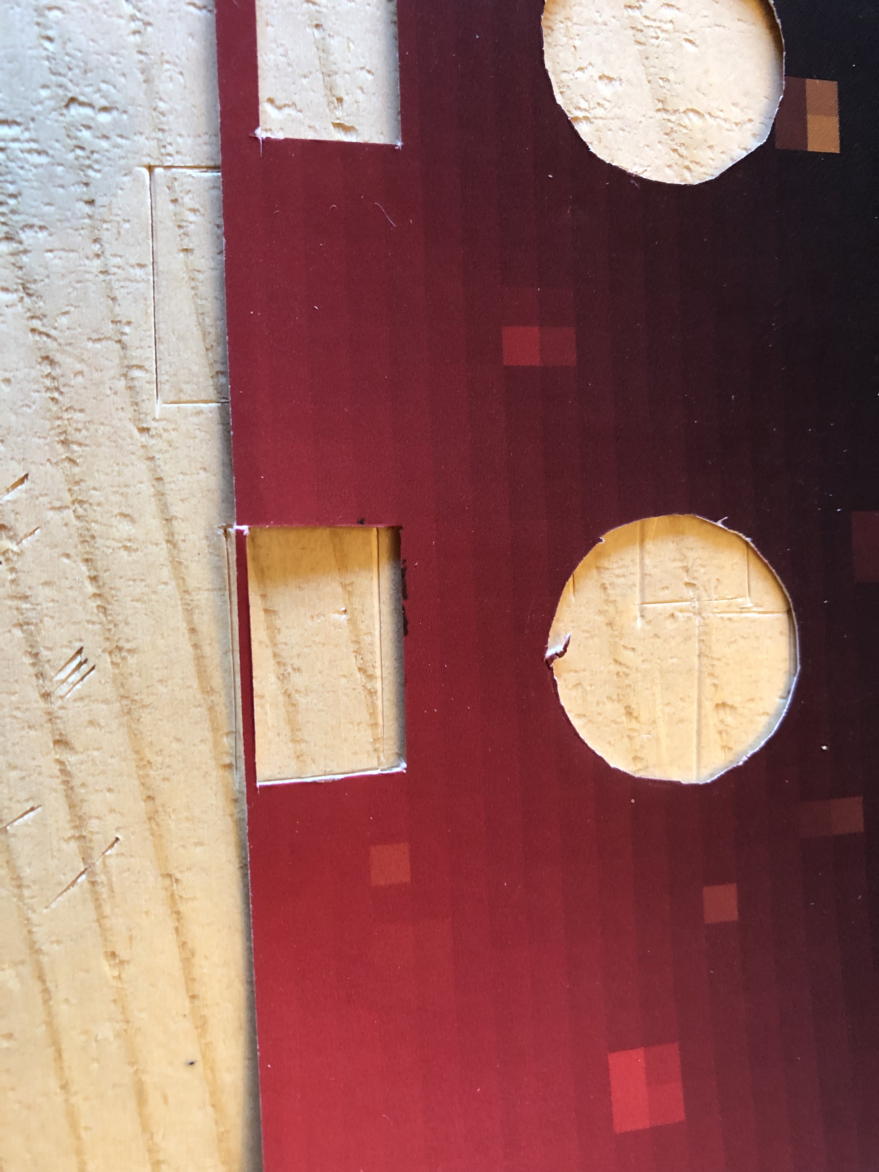
I marked the corners of the rectangles, and then used a straight edge and Xacto knife to cut them out. One of the rectangles ended up closer to the edge than it would have liked:
Here is the paper with all the rectangles cut out:


In order to completely block out the light that had been leaking from the sides of the LCDs, I put electrical tape on the back of the paper next to the rectangle cut-outs.

I was about to put the paper back on the control panel when I noticed that one of the LCDs had come unglued from its board.


It didn’t look like any of the electrical connections were damaged, so I powered up the LCDs to see if it would still light up.

It seemed to be working, so I went ahead with the control panel assembly. I didn’t bother gluing the screen back down, since the plexiglass should hold it in place. The next step was to put the paper on the control panel, then add the plexiglass, and the put all the buttons in and tighten them down.

With it all assembled, I powered on the LCDs to see how well my rectangular holes lined up. They lined up really well. And the light leaking from the side is no longer visible, so the electrical tape worked.


Even in low light, the bright spot next to the screen is now blocked out. Up next: lots and lots of wiring on the back of the control panel!

 My Arcade Machine Build