It’s been a few years since my last post in this topic. After I got the control panel to the point that it was in the last post, I spent an hour or so connecting all the data lines for the displays on one side of the panel. I fired up the emulator and … the displays went wonky. They didn’t display what they were supposed to, they kept changing even though I wasn’t changing games, and the images looked corrupted.
It was really disheartening. In order to check whether the images were actually corrupt, I had to get to the micro-SD cards, which meant completely disassembling the panel. I did that, but now I don’t remember if I checked any cards once I had it apart. I knew I would need a solid block of time to do some uninterrupted debugging, so I put it all away until I could actually dedicate some time to it.
And here I am, just over three years later, having not gotten to it. I do have a dedicated space to work on it now (having moved to a new house in 2020), so I don’t have to put it all away every time I work on it. Life has been crazy, but a week or so ago I connected the Raspberry Pi to the display and powered it up and played a couple of games with a NES-style USB controller. I decided to start working on it again, finally.
I wanted to figure out a way to be able to access the micro-SD cards without completely tearing the control panel apart, so I did a google search on “micro SD extension”. After sifting through the results and seeing a few that probably would not fit where I need them (including the one from Adafruit), I found this one:
I ordered one, and tested out by using it in the Raspberry Pi itself. And here it is, working:
So I can cut more slits in the bottom layer of the control panel and have all the micro-SD cards hanging down into the space below the panel. Then I can get to them when I need to without a full disassembly. I just need some time to be able to buy 19 more of these. So the next update might not be for a while, but I hope it’s significantly less than three years!
I corrected the power connections on the LCDs that were incorrect. Then I powered up the system and ran my demo Python script to get power to the LCDs. But instead, the relays kept clicking off as soon as they clicked on. I guessed that there was a short in the system, and since I had just soldered power wires onto the Arduino mount board for the blue (player 2) side, I took a look at that board.
I found a couple of spots where it looked like the positive and negative side strips had been inadvertently connected. I used a knife to break these connections. I tested with my multimeter to make sure the shirt was no longer there (something I really should have done in the first place, before powering it up) and then tried again.
As can be seen, it worked!
Once I had power to all the LCDs, I could light them up and use them to mark the locations for cutting out rectangles in the paper overlay. Of course, I needed a paper overlay. I asked my daughter to make something cool, and she whipped this up in under 20 minutes:
I took the image to Staples and had it printed. Then I used the plexiglass to mark holes in it for the buttons. The design has too much black to mark on the front, as can be seen here:
So I flipped over the paper, and flipped over the plastic (so I would get the correct hole locations instead of a mirror image).
I cut out the circles with an X-acto knife, cutting on the outside of the pen marks.
I put the paper on the control panel and put the plexiglass over it. I think it’s looking pretty good!
I removed the plexiglass and put all the buttons in place to hold the paper. Then I powered on the LCDs to see if they would shine through the paper well enough to mark their locations. They shone through better than I had expected.
In fact, they shone through a little too well. I was hoping that the paper would mask off the part on the side of the LCDs where lots of light leaks through. But you can see a little bright spot next to each of the displays. It is particularly obvious in this picture:
I marked the locations with a silver gel pen, since markings from a regular pen would be hard to see. Since the line is a little thick from the gel pen, I tried to keep the marking completely inside the rectangle that would be removed.
I marked the corners of the rectangles, and then used a straight edge and Xacto knife to cut them out. One of the rectangles ended up closer to the edge than it would have liked:
Here is the paper with all the rectangles cut out:
In order to completely block out the light that had been leaking from the sides of the LCDs, I put electrical tape on the back of the paper next to the rectangle cut-outs.
I was about to put the paper back on the control panel when I noticed that one of the LCDs had come unglued from its board.
It didn’t look like any of the electrical connections were damaged, so I powered up the LCDs to see if it would still light up.
It seemed to be working, so I went ahead with the control panel assembly. I didn’t bother gluing the screen back down, since the plexiglass should hold it in place. The next step was to put the paper on the control panel, then add the plexiglass, and the put all the buttons in and tighten them down.
With it all assembled, I powered on the LCDs to see how well my rectangular holes lined up. They lined up really well. And the light leaking from the side is no longer visible, so the electrical tape worked.
Even in low light, the bright spot next to the screen is now blocked out. Up next: lots and lots of wiring on the back of the control panel!
I got tired of trying to refine the locations of the rectangles for the mini LCDs. I thought it might work out better to just place the artwork that I am going to use over the panel and trace the lit-up screens through the paper.
It was also difficult to keep the LCDs in place without anything rigid covering them.
So I bought a piece of plexiglass. The smallest size that would cover the panel was 30”x36”.
I clamped the plexiglass to the top layer of hardboard from the control panel so I could trim it.
Once I had trimmed off 2/3 of the plexiglass, I still had to trim a little off of the edge.
It didn’t go as cleanly as I would have liked, but I got it done.
The next step was to drill the holes for the buttons. I left the plexiglass clamped to the hardboard to use the holes in the hardboard as guides for drilling the plexiglass. The problem is that the arbor for the hole saw would be in the way, and without the arbor, The drill would have no way of grabbing the hole saw. I noticed that the arbor had a set screw in it, which seemed to hold in the bit.
I loosened the set screw and removed the bit. Then I put the hole saw on.
I put the hardboard and plexiglass on top of a piece of wood to prevent excess pressure on the plexiglass and to have something that could be drilled into a little after cutting completely through the plexiglass. This part went really well.
I finished drilling the holes outside, because drilling through the plexiglass seems to melt it a little bit, and that smell is unpleasant. Here it is with all 20 button holes drilled:
I peeled the protective film off of both sides of the plexiglass, and I was very pleased with how good it looked.
Then I realized that I had not cut any holes for the joysticks. To mark a location for drilling those holes, I grabbed the paper that I had been using for figuring out where to cut out rectangles for the LCDs. I put the bit back in the arbor and drilled from the back of the plexiglass.
I had previously cut out a section of cardboard to go in between the layers of hardboard on the “player 1” side. In order to continue assembling the panel, I had to do this for the “player 2” side.
Before putting the LCDs in permanently, I had to load up all the images onto the micro SD cards. Since each LCD gets only the images for the button that it’s next to, I marked the backs of the LCDs so I would be able to put them in the correct spot once the images were loaded.
I assembled the control panel, without the graphics, so that I could wire power to all of the LCDs. Then I will be able to remove the plexiglass, overlay the graphics, and mark the locations of the LCDs (assuming they are bright enough to show through).
Here is the back of the control panel at this point. Lots of work left to do!
The next thing I needed to do was solder on wires for powering the LCDs on the blue side ( you can see in the previous image that there are a bunch of black and red wires under the red buttons, but no comparable bundle under the blue buttons).
And finally, here is the back of the control panel with power wires up to all the LCDs. End of Part 1.
Addendum: after posting this blog entry, I noticed that the wiring is incorrect for the top row of LCDs on the blue side. I will have to fix that before continuing.
One thing that became apparent when I was testing out the locations of the cutouts for the LCDs is that the LCDs being thicker than a layer of hardboard made that process difficult. So before continuing on that, I decided to resolve the thickness problem. I found a thin piece of corrugated cardboard and cut it to cover the buttons/LCD area.
I traced the shape of the holes onto the cardboard and cut it out. Then I put the cardboard between the two layers of hardboard.
I did a little extra trimming, because the cardboard was still sticking out into the LCD area in a couple of places. The difference is not easy to see between the picture above and the one below, but the difference is there.
Finally, I adjusted the locations of the rectangles in Photoshop, and printed and cut oput a new template. The next step, of course, will be to put the template on the control panel as before, power up the LCDs, and see how close I am.
Most of the wires that go to the LCDs will come off of the Arduinos, but not the power wires. For those, I will solder them to the boards that the Arduinos are on. The first step for that is to remove the Arduinos and unscrew the board from the back of the control panel.
Arduinos have been removed
I am using the prototype wires that I bought because of the sockets on the end that are perfect for connecting to the pins on the LCDs. I cut off the connector on one end, stripped it, and tinned it with solder to make soldering to the board go easier.
Here is the board with half of the black wires soldered on. Since the board has a copper strip with no solder mask, it’s really hard to make this soldering job look neat. The solder just flows too well across the copper.
And here it is with all 10 black wires and all 10 red wires soldered in:
Because the soldering is a bit messy, I used my mulitmeter to ensure that the red and black groups are not accidentally connected to each other.
I screwed the board back to the control panel, put some LCDs in place, and started wiring them up. I started with the power leads.
It quickly became apparent that wiring up the displays without them being securely mounted would not be practical. But in order to securely mount the LCDs, I need the acrylic overlay that I will be using, and under the overlay I need the paper that will have all the cool graphics and also mask off the LCDs so that only the viewable area will be seen.
So I started working on getting the proper layout for masking off the LCDs. I started by printing out another copy of the image that I had used to make the holes for the buttons and the LCDs. Then I cut out the button holes and small rectangles with an X-acto knife. The lines for the buttons are pretty thick and I wasn’t sure at first whether I should cut along the outside or inside of the line. I did the first button on the outside of the line.
I put one of the buttons in the hole to see how it fit. I realized that I should have used the inside of the line.
So I cut the next hole on the inside and it fit much better.
That second hole was a little sloppy, so I did the rest under a magnifying glass. I used a straight edge to help cut out the rectangles.
I put the paper over the control panel and inserted the buttons to keep it in place. Then I powered up the LCDs to see how well the rectangular holes lined up. The answer was that they did not line up very well.
I got out the calipers and measured how far off I was. Interestingly, all of the displays on the bottom row had the same offset, and all of the top displays had the same offset, but the offset for the bottom row was different from the offset on the top row.
I used the measurements to adjust the locations of the rectangles in Photoshop, and printed a new image. I have not cut that one out yet, so the next entry here will be about the continuing fine tuning of the rectangle locations.
A final note – I need to be more careful when arranging the LCDs in the control panel. I don’t want to break another micro SD card.
Now that the images are all ready, it’s time to solder leads onto the LCDs. The prototype board is really useful for holding the leads in place for soldering. I found that I could fit five sets of leads across the prototype board and still have adequate room between them.
I borrowed a lighted magnifying glass from my son-in-law so I could see better what I was soldering. It made the process so much easier.
Now that I have all the holes cut out for the LCDs and the wires for the LCDs, the logical next step seems to be to solder all the connections onto the LCDs and continue building the control panel. However, that would be getting ahead of myself. Once I finished all the cutting, I still did not have most of the images that I will be using. If I put the panel together before creating all the images, I would have to disassemble it to add the images.
So I spent a lot of time making images. I created a spreadsheet to keep track of what images would be used for each button, and to keep track of which ones I have completed. If a button is not used for a particular game or system, I put “none” in the box and made it pink. Once I had created an image, I highlighted the box that referred to it in green. Here is an image of the top part of the spreadsheet. Everything is green because I did this capture after I made all the images:
When I finished cutting the holes for the wires for the LCDs, I had not even filled out what all the button labels would be. Here’s what the spreadsheet looked like at that time:
I tried to make all of the labels interesting; since I am putting some effort into this part of the project, I decided to make it as cool as possible (I was inspired by my son-in-law who suggested making the Pac-Man text in the colors of the ghosts from the game. It then occurred to me to use a Pac-Man font, and things went from there).
I owe a great deal to the website gamesdatabase.org for helping me figure out what each button should be used for and what image to use for each button. I also got some help from arcade-museum.com and a few other websites for specific games.
In some cases, I gave up on making unique button labels. Galaga, Galag3, and Galaxian all have the same images. Here are the results for button 5, button 9, and button 10:
Button 5Button 9Button 10
As can be seen in the spreadsheet, some buttons do not have nearly as many images, since they are only used for a few games/systems. For example, here is button 1:
Button 1
This part took a long time, and I worked on it a bit at a time, grabbing a few minutes here and an hour or so there. I am so glad to be done with this portion. I am very pleased with how this turned out, and I am excited to get on with assembling the control panel.
Now that the top layer of hardboard for the control panel had all the cut-outs for the mini LCDs, it was time to cut holes in the bottom layer to accommodate the wiring. The first step was to remove all the hardware that was attached to the bottom layer. Here is all the hardware after removal, hopefully still properly connected:
I connected the two layers of the control panel together, using the four small buttons to keep things aligned. To mark exactly where the hole for the wiring would go, I put an LCD with wires attached to it and lined up my compass to mark the location.
I could now use these marks as guides to drill some starter holes on the bottom layer. Then I would use a dremmel tool to make the long, narrow hole. It soon became obvious that this approach was not practical, because many of the rectangular holes in the top layer do not have a place to mark for the wires, because they connect to another hole.
I thought about it for a bit and decided to trace the rectangular holes onto the bottom layer and then just is that as my guide. It’s more prone to error, since the display would not be held in place by the cutout while I was trying to mark wiring locations, but I decided to try it.
So now I had to hold the LCD with the wires on it inside the appropriate rectangle, and not allow it to move while I marked the wire location.
The problem with this approach is that the compass is now high enough above the surface that I am trying to mark, that I can’t be sure that my pencil is properly aligned to make the mark. I decided to just do this based on measurements. I decided that the outside of the wiring was close enough to the edge of the board that I could treat it as if it were all the way to the edge. For the inside of the wiring, I measured how far it was from the top edge with calipers.
Then I used the jaws of the caliper to mark where the wires would be.
Once I marked either side of the rectangle, I used my straight edge to draw the line connecting the marks.
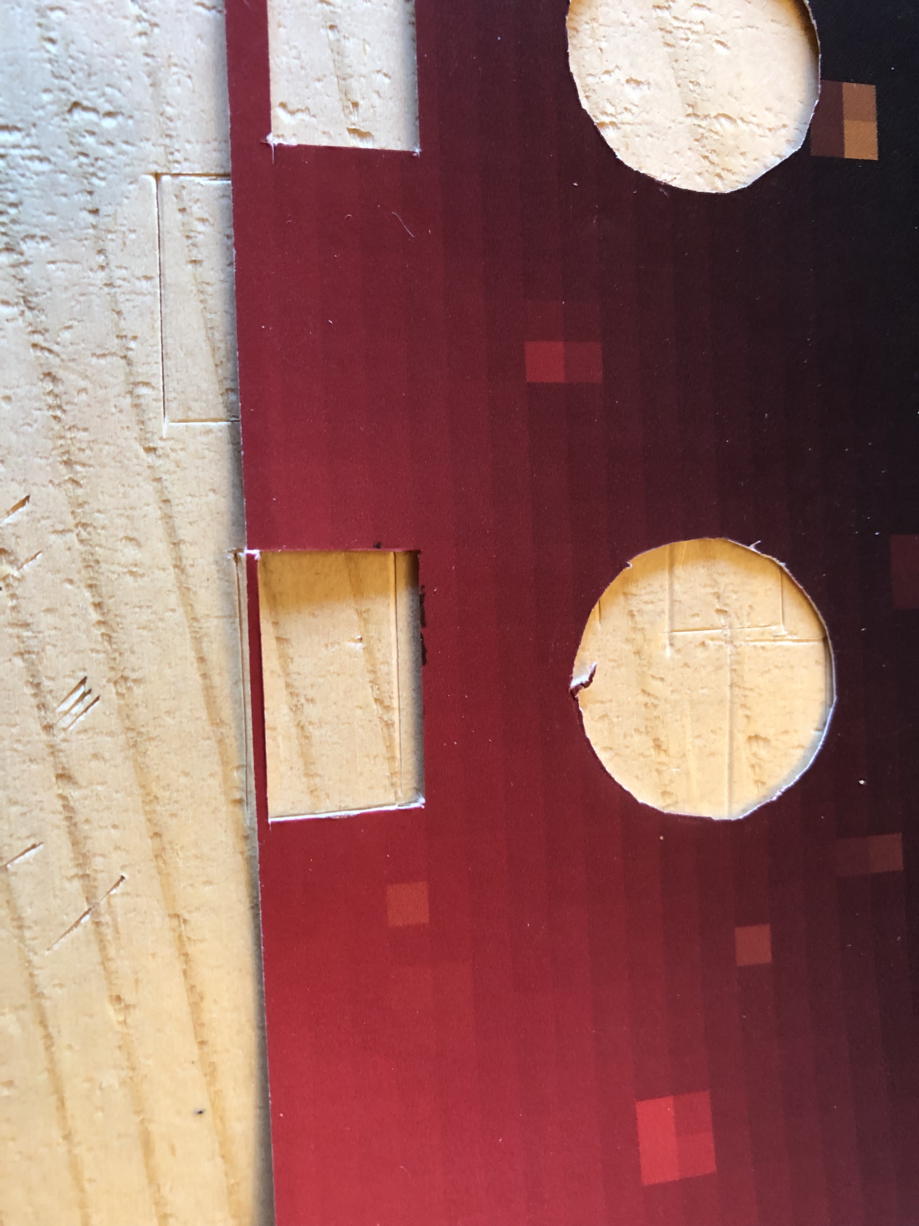
I decided to go ahead and cut this first hole before marking all the others, just to make sure that it would work. I drilled holes on either end, but the dremmel didn’t work out. If I had it on a high speed, it made smoke come out of the hard board. If I slowed it down enough to not make smoke, it cut too slowly. So I was back to the utility knife.
And here’s how it looks with an LCD in it with wires attached:
That seemed to work out pretty well, so I proceeded with all the other holes. At one point I switched from measuring from the top of the rectangle to measuring from the bottom, because for one of the rectangles, the top line was wonky. Here is the result:
I cut out the rest of the holes in the top panel layer for the LCDs. I occasionally placed the LCDs in the holes to ensure the fit. Here is a series of photos of the progress:
I had originally planned to put the LCDs for the start and select buttons on the sides, but I decided it wouldn’t fit too well:
Placing them below didn’t look promising either:
So I went with “above.” I decided to have the wires for the LCD near the button so they would not be on the edge. Here is the first side all cut out with the screens sitting in place: