There are several images for the buttons that have stylized text (like the “B” button for NES). My original approach to these was to find an image of the actual controller, and try to create a nice image based on that, tracing it out in Photoshop and using color fill. Those turned out to look amateurish at best. Then it occurred to me that there might be fonts that match what was used on the actual games, and I was right. The images resulting from just typing the letters in the correct font came out much better.
Lighting up the buttons
Now that I had pretty much worked out all the details of the mini LCDs, I decided to turn my attention to lighting the LEDs in the buttons based on which game was being played. A side note: it was around this time that one of my coworkers asked me why I was controlling the LCDs with those 7 input pins instead of just using the I2C interface. I answered him honestly: because I had not heard about it until that moment. He suggested looking into it, because I may be able to send the images over that interface and not have to buy an SD card for each LCD. I did look into it, and it was quite challenging. Now, I’m not one to back down from difficult technical challenges, but it’s hard to keep motivated when you already have an alternative solution that works.
So I started reviewing the page I had referenced for the LCDs, and looked at the various PACdrives that were available. And then it occurred to me – I already had a 7-bit binary output on the Raspberry based on which game is loaded. Maybe I could just use that! In fact, I could make a logical truth table for each button, then use Karnaugh maps to reduce the complexity of the combinatorial logic, and use the result to make a logic array out of relays to control the power to each LED!
After a few seconds of thought, I abandoned this hair-brained idea. Leave it to me to come up with the most complicated solution right off the bat! I remembered that I already have several highly sophisticated micro controllers doing things based on which game was loaded, and that each button already had its own micro controller. It would be much simpler to use this sophisticated circuitry that already existed than build a much larger and cruder circuit.
The problem is that I would need to connect one pin from each Arduino to its respective button. I still had some unused pins available, but they were not accessible due to the headers that I had soldered onto the Arduinos. I had only left available the pins I was already using. I thought I could maybe repurpose one of the comm pins on the end of the board, but those are apparently not set up to provide the current required by an LED.
The software change was small. The method that draws the image simply exits if it doesn’t find the specified file. I changed it to return an int, and set it to 1 if it doesn’t find the file, and set it to 0 if it does. Then, after I call the method to draw the image, I set the output pin to high of it was successful and low otherwise. In the end, it was only a few lines of code. The most recent version of the Arduino code is in a comment, including this change. The part where I light up an output pin is at the very end, beginning with if (success==0). There are a few other code changes, like having the bmpDraw method return a value, and setting up the A0 pin as an output. As for finding a pin to connect to, my solution is shown in these photos:


Yep, I just bent one of the pins on each of the headers.
Changing the display when the game starts
So far, every time I had loaded an image onto the mini LCD, it had been without regard to the loading of games, which was the original intent. Now that I had solved most of the problems regarding displaying images, I could focus on that. I referred again to the page I had found about lighting the LEDs in only the buttons that are to be used for a given game. Here is the link again: https://gist.github.com/savetheclocktower/c7644597c9c4c3990b7fee363d5f03c1
From that page I learned that in
/opt/retropie/configs/all, there are two files called
runcommand-onstart.sh and
runcommand-onend.sh. As their names would imply, the first script is run when a game is launched, and the second one is run when a game is exited. EmulationStation (which is the front-end interface to the emulators) passes critical information to the onstart script, like which system is being run. Here is my version of that script:
#!/bin/bash# ARGUMENTS, IN ORDER:# 1: System (e.g., "arcade")# 2: Emulator (e.g., "lr-fba-next")# 3: Full path to the game (e.g.,/home/pi/RetroPie/ropms/arcade/wjammers.zip)if [ -z "$#" ]; then exit 0fisystem=$1emulator=$2# Gets the basename of the game (e.g., wjammers")game=$(basename "$3")game=${game%.*}gamepath=$(dirname $3)# echo "system is $system"# echo "game is $game"# echo "gamepath is $gamepath"/home/pi/bin/loadButtons.sh "$system" > /home/pi/bin/log.txt
So all I am really doing is getting the system from the input and then calling another script called loadButtons.sh with that system as an input argument. Here are the contents of loadButtons:
#!/bin/bashsystem=$1gameline=`grep "^$system " /opt/retropie/configs/all/buttons.cfg`echo "gameline is $gameline"gameNumber=$(echo $gameline | cut -d ' ' -f 2-)echo "Game number is $gameNumber"binaryNumber=`echo "obase=2;$gameNumber" | bc`echo "Binary Game Number is $binaryNumber"python /home/pi/bin/setButtons.py $binaryNumber
So the first thing I do is use grep to find the system name in a file called buttons.cfg. That file contains lines like the following:
atari2600 1
So each line contains a system name and a number. This number is the same one that is computed in the Arduino from the input pins. The next line in the script (after grep) parses out the number from the line that has been extracted from buttons.cfg. The next line converts the number into a binary representation of that number (basically the opposite of the method on the Arduino that computes a number from the inputs). This conversion uses a command-line calculator called bc (for basic calculator). I had to install this, which was accomplished with the following command:
sudo apt-get install bc
Next, a Python script is called with that binary number as an input argument. Here is the content of that script (remember that the relays are asserted on low, so setting the output pin high turns them off and setting it low turns them on:
import RPi.GPIO as GPIOimport timeimport sysif len(sys.argv)!=2: print("Must have exactly one input arg") sys.exit()# reverse the order so that we start with the LSB in the loopnum=sys.argv[1][::-1]pins = [16,20,21,5,6,13,19,26]pins = [26,19,13,6,5,21,20]print 'Number is', numGPIO.setmode(GPIO.BCM)GPIO.setwarnings(False)GPIO.setup(16,GPIO.OUT)GPIO.setup(20,GPIO.OUT)GPIO.setup(21,GPIO.OUT)GPIO.setup(5,GPIO.OUT)GPIO.setup(6,GPIO.OUT)GPIO.setup(13,GPIO.OUT)GPIO.setup(19,GPIO.OUT)GPIO.setup(26,GPIO.OUT)GPIO.output(16,GPIO.HIGH)GPIO.output(20,GPIO.HIGH)GPIO.output(21,GPIO.HIGH)GPIO.output(5,GPIO.HIGH)GPIO.output(6,GPIO.HIGH)GPIO.output(13,GPIO.HIGH)GPIO.output(19,GPIO.HIGH)GPIO.output(26,GPIO.HIGH)GPIO.output(16,GPIO.LOW)counter=0for c in num: pin = pins[counter] print "Setting pin {}".format(pin) #print 'setting pin:' str(pin) if c == "1": GPIO.output(pin,GPIO.LOW) if c == "0": GPIO.output(pin,GPIO.HIGH) counter += 1
The first thing done in this script is to reverse the order of the input. The reason for this is that, for example, if the input is “1011”, which is equivalent to the decimal number 11, I don’t have enough bits to set all of the output pins. There are seven output pins that need to be set, but I only have four bits in the input. In order to set all the pins, I would need leading zeros, so the input would be “0001011”. Then I could go through and set the first three pins to zero (high), the next one to one (low), then zero, then two ones.
Instead of trying to zero-pad the input, it made more sense to just reverse the order of the input, set all the pins to zero (high), and then go through the input (in reverse order now) and once you get to the end of the input, you’re done.
Once the input has been reversed, I set the required pins as outputs, and then set them all high.
The next step is to set pin 16 low. I don’t think I’ve mentioned this before, but I only needed 7 pins for controlling the Arduino, and the bank of relays that I bought has 8 relays on it. I decided to use the 8th relay to switch the power to all the Arduinos and displays. So when no game is running, that will all be off. Setting pin 16 low here will turn on the power to those devices.
The last part of the script loops through the input.
The scripts for turning the LCDs off are much simpler. Here is runcommand-omend.sh:
#!/bin/bash/home/pi/bin/resetButtons.sh
And here is resetButtons.sh:
#!/bin/bashpython /home/pi/bin/resetButtons.py
And here is resetButtons.py:
import RPi.GPIO as GPIOimport timeimport sysGPIO.setmode(GPIO.BCM)GPIO.setwarnings(False)GPIO.setup(16,GPIO.OUT)GPIO.setup(20,GPIO.OUT)GPIO.setup(21,GPIO.OUT)GPIO.setup(5,GPIO.OUT)GPIO.setup(6,GPIO.OUT)GPIO.setup(13,GPIO.OUT)GPIO.setup(19,GPIO.OUT)GPIO.setup(26,GPIO.OUT)GPIO.output(16,GPIO.HIGH)GPIO.output(20,GPIO.HIGH)GPIO.output(21,GPIO.HIGH)GPIO.output(5,GPIO.HIGH)GPIO.output(6,GPIO.HIGH)GPIO.output(13,GPIO.HIGH)GPIO.output(19,GPIO.HIGH)GPIO.output(26,GPIO.HIGH)
And finally, here is a video of it all working:
Scaling Up: Multiple LCDs
Now that I had a good idea about how I could display all the images I needed to for a single button, it was time to think about how I could do multiple buttons. It didn’t seem practical that I would be able to use one Arduino to control more than one LCD. The problem, though, is that an Arduino Uno is kind of bulky, and I didn’t want to have to use 20 of those. But when I was at Micro Center, I had seen a smaller version called the Arduino Pro Mini. These are much smaller, and much less expensive, but they have the same processor and memory and clock speed as the Uno. So I ordered three of them from Amazon:

One drawback of these Arduinos is that they do not have a USB port on them, so you have to buy a USB-to-serial converter in order to program them from your PC:

Also, these Arduinos come with none of the pins soldered on. Here is a picture of me soldering pins on an Arduino Pro Mini just a few days before Halloween:

During all this time, I had also been working on figuring out which buttons would perform which functions for each of the consoles that I am emulating. I still have to work that out for all the arcade games. In most cases, once I figured out which function a button would perform, I would then create an image for it that will be displayed on the LCD. I made a spreadsheet to keep track of all of that.
Here is a photo that shows that the small Arduino can still control the display (this time with an image for SNES). At this point, I have only hooked up power from the Raspberry to the Arduino, and the control pins are all connected directly to 0V or 5V.

And here is where some serendipitous simplicity kind of fell into place. Since the images are being stored on SD cards that are located on the LCD, each Arduino could be running the exact same code, and it wouldn’t matter which display was connected to which Arduino, because I could make the file names the same on all the SD cards, even though the actual image in that file would be different for each SD card. For example, here are the images that I created (so far) for the bottom left button and the one next to it (which I have designated buttton 5 and button 6):


I was worried that one Raspberry Pi would not be able to provide enough current to drive 20 Arduinos, so I decided to use a bank of relays in between the Raspberry and the Arduinos. That way, the Raspberry would only have to drive the relays, and the Arduinos could have a completely separate power source.
Here is a (boring) video of the Raspberry controlling the relays. I realized after some initial frustration that the relays assert low; in other words, you have to set the control voltage to 0 to switch the relay and to 5V to release it. So in my python script on the Raspberry, I had to swap all the GPIO pin settings (where I was setting them low, I had to set them high, and vice-versa).
Here is how it looks connected to the Arduino:

The relays are single-pole, double-throw (SPDT), which means that there is a common contact that is connected to one side when the relay is not activated, and connected to the other side when it is activated. This is perfect for me, since I want each input to be connected to either 5V or 0V depending on the game that is selected. So the loopy red wires that you see in the image are connecting the first side of each relay to 5V, and the black loopy wires are connecting the other side of each relay to 0v. Then the common contact goes to the Arduino.
The only hard part now is that I would have to connect each of the common contacts on the relays to the same pin on each of the Arduino boards. My first idea was to create a circuit board that I could solder all of the Arduinos onto (I actually planned to solder sockets onto the board so that I could easily remove the Arduinos for reprogramming or replacing, if necessary). I found some PCB layout software and spent a lot of time building the layout that I would need. I ended up with this:

That’s not quite complete, since a few of the Arduinos still don’t have the header for connecting to the LCD. I was discussing with a friend about how I would actually get the board made after I was done with the design, and after asking a few questions about exactly what I was doing, he asked, “Why don’t you just use long-lead headers and stack them?” Here is what he was talking about:

I realized that his idea was perfect. I could use those for the pins that have to all be connected together, and some 90-degree connectors for the pins that have to go to the display. I ordered some of these stack-able headers and some 90-degree connector pins. I also ordered some more Arduinos (still not up to 20 – I have some budget contraints!). The following photo is in preparation for soldering. I am using an 8-pin header on one side and a 10-pin header on the other because of which pins I need available for connecting to the display.

Here is what my Arduino Pro Mini looked like when I was done soldering:

And here is how it looked when I had a few of them done:


You see that small bit of solder in the last image? Yeah, that’s the last of my solder. So I only got four done. Also, I decided that I will not try to put all 20 Arduinos in a single stack, as that seems structurally unstable. Instead, I will probably have four stacks of five, and run wires between the stacks to keep everything connected.
I bought a small piece of thin wood to mount my components on, since this is starting to get complex. I don’t know whether the board that things are mounted on now will end up in the final build, though. There are also two more wires on the board with the relays; a black and a red wire that loop from one side of the board to the other. This is to allow the Raspberry to only have to drive optocouplers instead of optocouplers and relay coils. It handled the relay coils just fine, but that was when it was not trying to emulate something like the N64.

Here is a photo of the LCD being connected directly to the Arduino instead of using the proto board (which will eventually go away completely):

And a close-up of the Arduino on the proto board, although the proto board is only being used to hold the Arduino. All electrical connections are now through the stack able headers:

Here is a photo of a stack of Arduinos, with the control wires connected to the top, but the display connected to the third one down. I don’t have a video proving that it still works in this configuration, but it does.

Finally, I ordered a second LCD so I could prove that I can drive two simultaneously, but I still don’t have any solder (I ordered a bunch on eBay, but it is taking forever), so I can’t solder the pins onto the new display to test it!
Controlling the Arduino with the Raspberry Pi
This step was pretty simple. All I had to do was look up how to set the GPIO pins on the Raspberry and then connect those pins to the Arduino. It turns out that this can easily be done with a simple Python script:
import RPi.GPIO as GPIO
import time
GPIO.setmode(GPIO.BCM)
GPIO.setwarnings(False)
GPIO.setup(16,GPIO.OUT)
GPIO.setup(20,GPIO.OUT)
print “black screen”
GPIO.output(16,GPIO.LOW)
GPIO.output(20,GPIO.LOW)
time.sleep(6)
print “NES B”
GPIO.output(16,GPIO.LOW)
GPIO.output(20,GPIO.HIGH)
time.sleep(6)
print “Kick”
GPIO.output(16,GPIO.HIGH)
GPIO.output(20,GPIO.LOW)
time.sleep(6)
print “Punch”
GPIO.output(16,GPIO.HIGH)
GPIO.output(20,GPIO.HIGH)
time.sleep(6)
print “done”
GPIO.output(16,GPIO.LOW)
GPIO.output(20,GPIO.LOW)
Here are a couple videos of the above script being run on the Raspberry while connected to the Arduino. The first video shows the image on the LCD changing (without me moving any wires), and the second video is the screen output (I was logged in to the Raspberry via ssh).
From here, it’s easy to scale up from four images (counting the blank screen) to as many as I need. As I pointed out before, each time I add an input pin on the Arduino, I double the number of possible combinations.
On my Raspberry, I have 16 consoles being emulated, and 54 arcade games, for a total of 70 different button configurations. If I used 6 input pins, that would only get me to 64 possible combinations on the input pins, which is not quite enough. So I decided to use 7 input pins, which will give me 128 possible combinations, but I will only use 70 of them.
The first part of this up scaling is to change the method on the Arduino that converts the pin states to a number:
int convertPinsToInt() {
int out = 0;
if (digitalRead(7)) out += 1;
if (digitalRead(6)) out += 2;
if (digitalRead(5)) out += 4;
if (digitalRead(4)) out += 8;
if (digitalRead(3)) out += 16;
if (digitalRead(2)) out += 32;
if (digitalRead(1)) out += 64;
return out;
}
Then, of course, I would have to add to the loop method to account for all the new cases.
Scaling Up: More Than Two Images
With one input pin, and two possible states of that pin, I can select between two images. If I add a second input pin, there are four possible combinations: both high, both low, first one high while the second one is low, and first one low while the second is high. Each time I add a pin, I double the number of possible combinations. For example, if I add a third pin, there are the four combinations mentioned above while the new pin is low, and those same four combinations while the new pin is high.
I wrote a method to convert the four possible combinations of two pins into a number between 0 and 3. Then I changed the loop method to display a blank screen for 0, “kick” for 1, “punch” for 3, and “B” for 2. Here is the conversion method:
int convertPinsToInt() {
int out = 0;
if (digitalRead(7)) out += 1;
if (digitalRead(6)) out += 2;
return out;
}
Also, at this point I am still not using the Raspberry. I just have two wires to move by hand.
Changing Images on the Mini Display
I have kind of glossed over using the Arduino to get the LCD to display an image. So I will go into painful detail here.
The Arduino is a micro controller, which is like a computer that can be assigned one task. The programming language is C++, which was nice to find out, since I have written C++ code professionally. The process is pretty simple: you write the code on a PC or Mac, and then you plug the Arduino into the PC with a USB cable, and click on the upload button. Then you resolve any errors it tells you about and try again.
On an Arduino, there is a method called “startup” and a method called “loop.” When it is powered up, it will execute whatever you have put in “startup” once, and then it will execute the instructions in “loop” over and over until you power it down. In the sample code from Adafruit, they loaded and displayed an image in the startup method and then did nothing in the loop method.
One more detail: the LCD has a micro SD card holder on the back, and the code provided by Adafruit loads image files from that SD card.
I made a couple of other images for testing purposes. I downloaded a font called Ka-Blamo! and used it to make these two images:


The font only creates white letters with a black exploding outline, so I used photoshop to change the colors.
I wanted to see what those images looked like in the LCD, but I hadn’t figured out how to change what was being displayed, so I changed the code for the Arduino and re-uploaded. Here is how it looks:


I will be posting all of my Arduino code in the comments of this post (eventually).
On to the problem of getting the Arduino to change what it is displaying based on something external to it. The Arduino has several pins that you can connect wires to. Some are labeled analog pins, and some are digital. These pins can be set up as input or output pins. There are also pins to provide power, some for communication, and a reset pin. So if I connected these pins to the Raspberry, I could change their state when games are loaded, and then have the Arduino change the file based on the state of the pins. Since the file was being loaded in the startup method, I would have to change the settings on the pins and then send a reset signal so the Arduino would reload with the new image. It didn’t take me long to realize that this was a terrible approach. After all, the loop method is there so that you can do things without reloading.
So I moved the loading of the image to the loop method. I didn’t want to load the image every time through the loop, since it loops several times per second. Also, it would be wasteful to keep reloading the same image, and in this case it would be annoying, since it takes so long to load the image. Instead, I decided to check the state of the input pins each time through the loop, and if they had changed, then load the appropriate image.
In designs like these, I like to start as small as possible and then build up once the smaller version is working. It’s easier to find errors if you don’t have as many places to look. So I started with only two images and one input pin. If the input pin was low (0V), it would display one image, and if the input pin was high (5V), it would display another image. I am still not using the Raspberry to control the input pin, because if it didn’t work, I wouldn’t know if the problem was in the Raspberry or the Arduino. Just another example of starting small and then building. So instead of using the Raspberry, I have a wire connected to the input pin, and I just use my hand to connect the other end of the wire to 5V or 0V. Here is a video of it working:
Getting the Display to Work
Since I couldn’t buy 20 of the mini LCDs all at once, I decided to get one working in the meantime. I soldered the connector pins on and plugged into a prototype board. Here it is, all ready to go:

I found a Python package online that someone had developed for the ST7735 chipset (which is what my display uses). They were successful at getting a 2.5″ display, also made by Adafruit, to display an image they chose. I tried to adapt the package to my display, but was not successful. Most of the time, the screen would remain blank, and if it ever did display anything, it looked like this:

Great. So now I can simulate an old TV with no reception. Except that it’s just a still image. Adafruit is very supportive of their products, and they have developed an entire graphics software library, but it is for micro-controllers, like the Arduino. I fought with this for a while, and finally decided to buy an Arduino and follow Adafruit’s online tutorial to just get something on the display. I purchased an Arduino Uno, and did just that. For my test image, cropped a high-resolution photo of an NES controller so that I just had the “B” label. It worked! I was so excited!

I was so excited, I made a short video of the image loading (I apologize in advance that many of my videos are in vertical mode):
Of course, now I still had a few hurdles to clear:
- The LCD is being driven by an Arduino that is completely independent of the Raspberry Pi that runs the games – I needed to get the Raspberry to control the Arduino
- As far as I could tell, the Arduino could drive exactly one display, and I was going to need 20 displays.
- The Arduino would load a single image when it was powered on and then do nothing else. This is less of a hurdle and more of more work needing to be done.
Button Labels
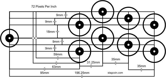
Before getting to the labeling of the buttons, I’ll talk a bit about the layout that I chose. I found this extremely helpful website: https://www.slagcoin.com/joystick/layout.html
The first thing to decide was how many buttons I would use for each player (I had decided that this would be a two-player arcade machine). Out of the consoles that I wanted to emulate, the one with the most buttons on the controller was PS1. There are the four action buttons (circle, X, square, and triangle), start and select, and two shoulder or trigger buttons on each side, for a total of 10 buttons. I decided to use an 8-button layout, because start and select could be placed just about anywhere, since they are not typically used during gameplay. I decided to go with this layout:
My first idea about having labels for the buttons on the arcade machine was to create thin overlays with holes in them. So you would have this stack of overlays and find the one that corresponded with the game that you were playing, and place that on the controls. I quickly abandoned this approach for several reasons. The biggest reason was that the idea of looking through a stack of overlays every time you want to play a game is so unappealing that it would probably never actually happen.
I thought that it would be really cool if the control panel could be changed electronically, but I didn’t think I could find an LCD that was approximately 12″x30″ and that you could drill holes in. Then I thought that maybe I could find individual LCDs that were small enough that I could put one next to each button, and change the display based on the game being played. I looked for the smallest LCD I could find, and I found this one:

https://learn.adafruit.com/adafruit-mini-tft-0-dot-96-inch-180×60-breakout/overview
This was pretty exciting. I could place displays below the bottom row of buttons and above the top row. They were small enough that they would fit without interfering with each other. They were a little pricey, but I could order them one at a time and eventually have all that I need.
Since I had already found the tutorial on lighting only the in-use buttons, I figured I could use some of that information to load displays when games are loaded.
Initial Plans
I don’t remember exactly when or why I decided to build an arcade cabinet for my Raspberry. In fact, there was a time when a friend suggested doing that, and I blew the idea off. But one day, I decided that it would be really cool to have an arcade cabinet.
In the meantime, I had purchased a different set of controllers, which were based on the PS2:

One of the things that annoyed me about this controller is that the buttons are labeled 1, 2, 3, and 4, which is not useful when playing a SNES game, for which the labels should be A, B, X, and Y, and it’s not useful when playing a PS1 game (The Raspberry isn’t powerful enough to emulate a PS2), for which the labels should be X, square, triangle, and circle.
My arcade machine would have the same problem; the buttons have different purposes based on which console or arcade game was loaded. Some buttons wouldn’t even be used for some games. For example, Street Fighter II uses six buttons, Altered Beast uses 3, Space Invaders uses 1, and Pac-Man uses none.
I eventually decided to get buttons with LEDs in them, because lighted buttons are cool, and if I was smart about it, I could only light the buttons being used.
There is a commercial software product called LEDBlinky which is designed for this exact purpose. It is designed to work with the PACDrive devices made by Ultimarc. LEDBlinky even addresses the problem of knowing what the buttons do by flashing them one at a time when the game loads and having a voice tell you what the currently flashing button is for. You can even get RGB LED buttons, so you can change the color of the buttons! It’s very cool!
I wasn’t sure I wanted to spend the money on LEDBlinky, so I kept searching for alternatives, and found this: https://gist.github.com/savetheclocktower/c7644597c9c4c3990b7fee363d5f03c1
This seemed like a good solution if all I want to do is light the in-use buttons and not have all the other flashiness. This is the solution I decided I would go with.
Another small detail I wanted was a button that would initiate the Linux shutdown on the Raspberry, so I could easily have a clean shutdown when I powered it off. That problem had already been solved here: https://pie.8bitjunkie.net/retropie-shutdown-and-startup-switch-the-easy-way
I followed the directions on that site and it worked like a charm the first time.
